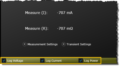
In the default view, the measured power, voltage, current, and resistance values for each channel are displayed. Use the "Measurement Settings", "Transient Settings", and "Advanced Settings" drop-downs to view additional instrument settings including voltage, current, and resistance levels and ranges on each load channel.
Note: Parameter choices vary by instrument. Some of the parameters listed below might not be available on your particular instrument. The bench application will list only those parameters, and parameter ranges, available for your particular instrument.
From the "Mode" drop-down for each load input, select the operating mode: CV (constant voltage), CC (constant current), CP (constant power), or CR (constant resistance). When programmed to a specific mode, the input remains in that mode until the mode is changed or until a fault condition, such as an overpower or over-temperature, occurs.
From the "Measurement Settings" drop-down, configure the voltage, current, power, and resistance levels and ranges on each load channel. When available, you can also enable Over Voltage Protection (OVP) and Over Current Protection (OCP) with corresponding levels.
BenchVue Tip: You can quickly increment or decrement a numeric value using the mouse wheel. Click once in a number entry field and then scroll the mouse wheel up or down.
From the "Transient "Settings" drop-down, set the transient levels for voltage, current, power, and resistance on the selected load channel.
You can select the Trigger Source for the entire instrument (applies to all modules installed in the mainframe). Below are the trigger source choices:
BUS – Accept a *TRG command or GPIB <GET> signal as the trigger source. This selection guarantees that all previous commands are complete before the trigger occurs.
LINE – Generate triggers that are synchronized with the ac line frequency.
HOLD – Triggers will be generated only by a TRIGger:IMMediate command on this mode. All other triggering commands are ignored.
EXTERNAL – Select the instrument's hardware Trigger Input as the trigger source. This trigger is processed as soon as it is received.
TIMER – Generate triggers that are synchronized with the instrument's internal oscillator as the trigger source. The internal oscillator begins running as soon as this command is executed. Use the TRIGger:TIMer command from the instrument to set the oscillator period.
EXT – Select any connector pins configured as trigger sources.
IMM – Generates a trigger as soon as the trigger system is INITiated
PIN <n> – Select a digital port pin configured as a trigger input where <n> indicates the pin number.
NOTE: This settings is only available for load model EL33133A, EL34143A, and EL34243A.
From the "Advanced Settings" drop-down, configure the ON delay and OFF delay.
Check ON/OFF Coupling to enable the coupling for the input channels.
To display voltage, current, and/or power traces on the bench application graph, check the "Log Voltage", "Log Current", or "Log Power" selection. Alternately, you can select the displayed traces from the "Data Log Trace Configuration" panel on the Data Logger tab.